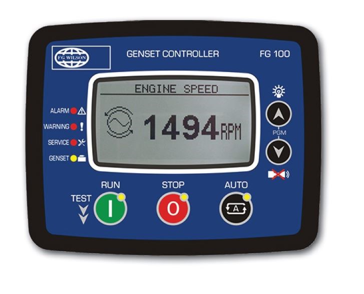
FG 100
Presentation
The FG Wilson DCP range allows you to monitor and control your generator set with ease, providing important diagnostic information whilst ensuring your unit operates within safe parameters.FG Wilson DCP digital control panels, provide simple, intuitive menu navigation and control of your generator set operations. Key information is displayed via the LCD screen and LED’s using universally recognised symbols, eliminating the need for complex instructions or language settings.
Benefits
- Automatic start control module
- Integrated metering & controls
- Monitoring, protection, operational status, fault conditions and metering displayed via LCD & LED’s
- Configuration of parameters via licence free software
- Robust electronics package
- Symbols for simple, intuitive control
Features
- Configuration of parameters by front panel push buttons or by PC via mini USB interface (DCP-10) or communication software (DCP-20)
- True RMS Voltage Sensing
- Engine & AC monitoring
- Run / Auto keys with LED indicators
- Under / Over voltage protection
- Larger 128×64 graphic LCD (DCP-20 only)
- RS485, RS232 or USB port for remote communication (DCP-20 only)
- Power metering (DCP-20 only

– FG Wilson DCP-10 is standard on 5.5 – 220 kVA generator sets range.
| FG100 | DSE4520 | DSE7320 | DSE7410 | DSE7420 | PW1.1 | PW 1.1+ | PW 2.1 | PW2.1+ | MRS16 | IG200 | EG2500 | |
| Control Function | Auto Start | Auto Mains Failure | Auto Mains Failure | Auto Start | Auto Mains Failure | Auto Start | Auto Start | Auto Start | Auto Start | Auto Start | Sync | Sync |
| I/O | ||||||||||||
| Digital Inputs | 6 | 4 | 8 | 8 | 8 | 4 | 6 | 6 | 6 | 7 | 8 | 10 |
| Dedicated E’stop Input | x | x | ✓ | ✓ | ✓ | ✓ | ✓ | ✓ | ✓ | x | ✓ | x |
| Digital Outputs | 5 | 4* | 6 | 6 | 6 | 6 | 6 | 8 | 8 | 6 | 8 | 11 |
| Dedicated Fuel And Crank O/Ps | x | ✓ | ✓ | ✓ | ✓ | x | x | x | x | x | x | x |
| Analog Input | 3 | 3 | 6 | 6 | 6 | 2 | 3 | 3 | 3 | 4 | 4 | 4 |
| Mpu Input | x | x | ✓ | ✓ | ✓ | ✓ | ✓ | ✓ | ✓ | ✓** | ✓ | ✓ |
| Rs232 | x | x | ✓ | ✓ | ✓ | x | x | x | x | Option | Option | x |
| Rs485 Modbus | Option | x | ✓ | ✓ | ✓ | x | x | ✓ | ✓ | Option | ✓ | ✓ |
| Can Bus Engine | ✓ | ✓ | ✓ | ✓ | ✓ | ✓ | ✓ | ✓ | ✓ | ✓ | ✓ | ✓ |
| 2Nd Can Bus | x | x | x | ✓ | ✓ | x | x | ✓ | ✓ | x | ✓ | ✓ |
| USB | ✓ | ✓ | ✓ | ✓ | ✓ | x | x | x | x | ✓ | ✓ | x |
| Ethernet | x | x | x | ✓ | ✓ | x | x | x | x | Option | x | x |
| SNMP | x | x | x | ✓ | ✓ | x | x | x | x | ✓ | ✓ | x |
| Power Measurement | ||||||||||||
| kW | ✓ | ✓ | ✓ | ✓ | ✓ | x | x | ✓ | ✓ | ✓ | ✓ | ✓ |
| kVA | ✓ | ✓ | ✓ | ✓ | ✓ | x | x | ✓ | ✓ | ✓ | ✓ | ✓ |
| kVAr | ✓ | ✓ | ✓ | ✓ | ✓ | x | x | ✓ | ✓ | ✓ | ✓ | ✓ |
| pf | ✓ | ✓ | ✓ | ✓ | ✓ | x | x | ✓ | ✓ | ✓ | ✓ | ✓ |
| kWh | x | ✓ | ✓ | ✓ | ✓ | x | x | ✓ | ✓ | ✓ | ✓ | ✓ |
| kVAh | x | ✓ | ✓ | ✓ | ✓ | x | x | ✓ | ✓ | ✓ | ✓ | ✓ |
| kVArh | x | ✓ | ✓ | ✓ | ✓ | x | x | ✓ | ✓ | ✓ | ✓ | ✓ |
| Event Recording And Plc Function | ||||||||||||
| Real Time Clock | ✓ | ✓ | ✓ | ✓ | ✓ | x | x | ✓ | ✓ | ✓ | ✓ | ✓ |
| Event Log | 400 | 50 | 250 | 250 | 250 | 40*** | 40*** | 40*** | 40*** | 350 | 350 | 300 |
| Plc Capability | x | x | ✓ | ✓ | ✓ | x | x | x | ✓ | ✓ | ✓ | ✓ |
* 2 are used if in Auto Mains Failure configuration
** Consumes 1 Analogue input
*** Has 40 event slots each of which can record up to 40 instances of an event


